
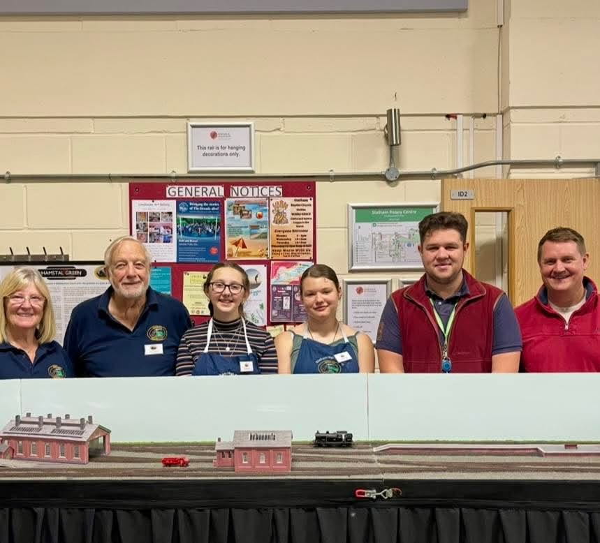
This layout was originally constructed by a team of students at Stalham High School under the guidance of a group of Club members. It is now part of the Club stock and work is continuing

The layout is a simple branch line terminus with a station, goods yard, loco shed and a carriage siding; with a fiddle yard using cassettes for maximum storage train lengths. It is designed to provide operational interest with opportunities for shunting, train variety and some scenic interest.
The fictitious location has been deliberately set in the era of the end of the Steam Age on British Railways (1955 – 1968) as this provides the most iconic operating and scenic opportunities. The modern railway in a similar environment would be very simple with Diesel Multiple Units and a single line track or could even have closed post-Beeching!.
September 2024
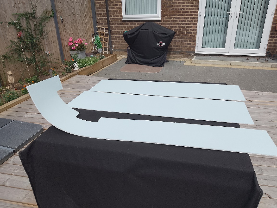
The project began with a team of 8 students and the first session was devoted to a demonstration of a working layout, allowing the students to operate it and learn the different aspects of creating a model railway. The next few sessions were taken up with carpentry and the building of the three baseboards using frames of 2″ x 1″ topped with 9mm MDF. All of the actual work was done by the students, measuring and cutting the frames and drilling and screwing them togther and then drilling and screwing the tops down. Then the boards had to be connected together, carefully aligning them and drilling for the locating dowels, followed by fixing the joining clamps. The standard of workmanship was very high indeed something we came to expect on all aspects of the project.


October/November 2024
At this point we asked the students to choose the method of point operation, perparing a mock-up of four methods to demonstrate the various aspects. We showed them wire-in-tube, Peco solenoids, Slow motion motors and servos controlled by Arduinos or MERG EzyBus systems. The students chose the servos and EzyBus controls so now we could move onto track laying.
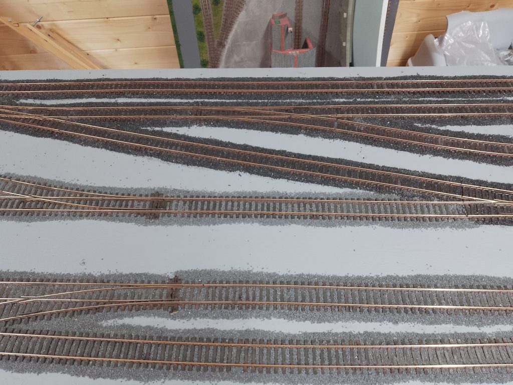
Next came marking out the track plan onto the baseboards and laying pieces of track roughly to check alignments and spacings. Holes were predrilled for point opeartion and wiring and then they started laying the track for real. Each piece required connecting to its adjoining piece and the points required special insulating joiners on the V-crossing (frog). They learned how to lay the track up to the board edge and align it to the next board using copper clad sleepers and rail joining aligners.


January 2025
Track laying continued, slow and painstaking work but they excelled at it and we ran a couple of wagons and a large loco around just to check it was snag-free – it was.


February 2025
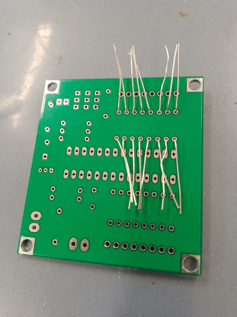
With the track laying complete and the point locations identified, we could now add the baseboard cross-bracing. The track was marked out with red and black marks to identify where the dropper wires would go. The students took it in turns to drill the holes for the droppers and then they laid the DCC bus wires – basically a ring of wire to carry the power to the track from the controller.


Next we showed them how to put together the MERG electronic modules, servo mountings and how to add them to the track. We also added all the dropper wires, frog connections and tested the electrical continuity. After a couple of corrections all was ready.


March 2025
While all this electrical work was proceeding, we introduced the subject of scenery and our Club Secretary, Rosemarie, showed them how to paint small figures. They really got into this and we also discussed the buildings and other scenery they wish to incorporate into the layout.


April – July 2025
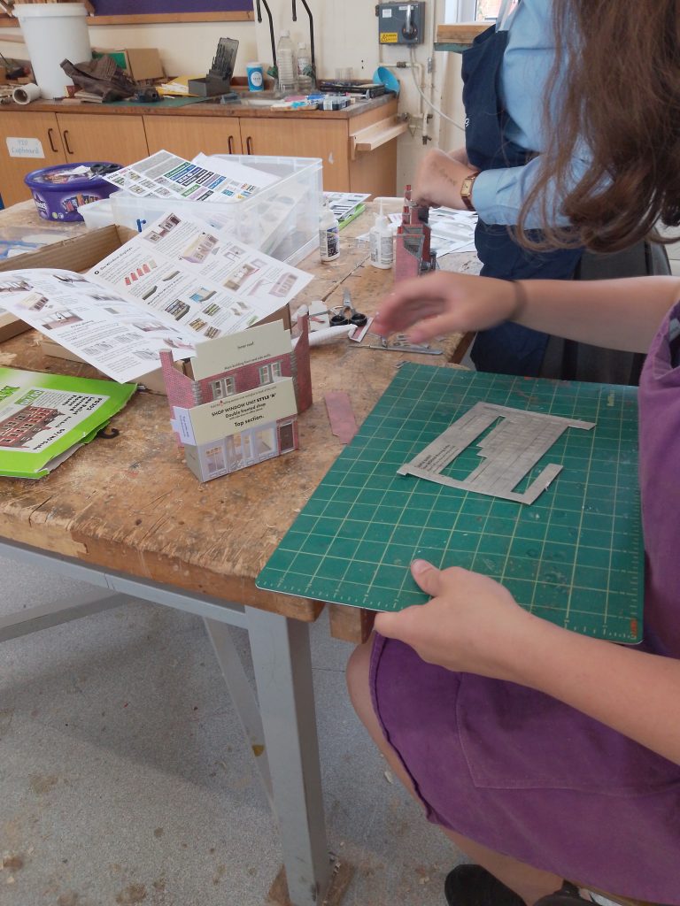
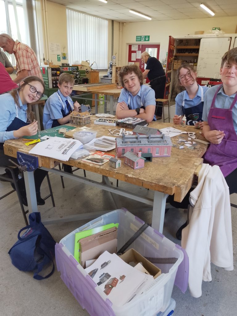
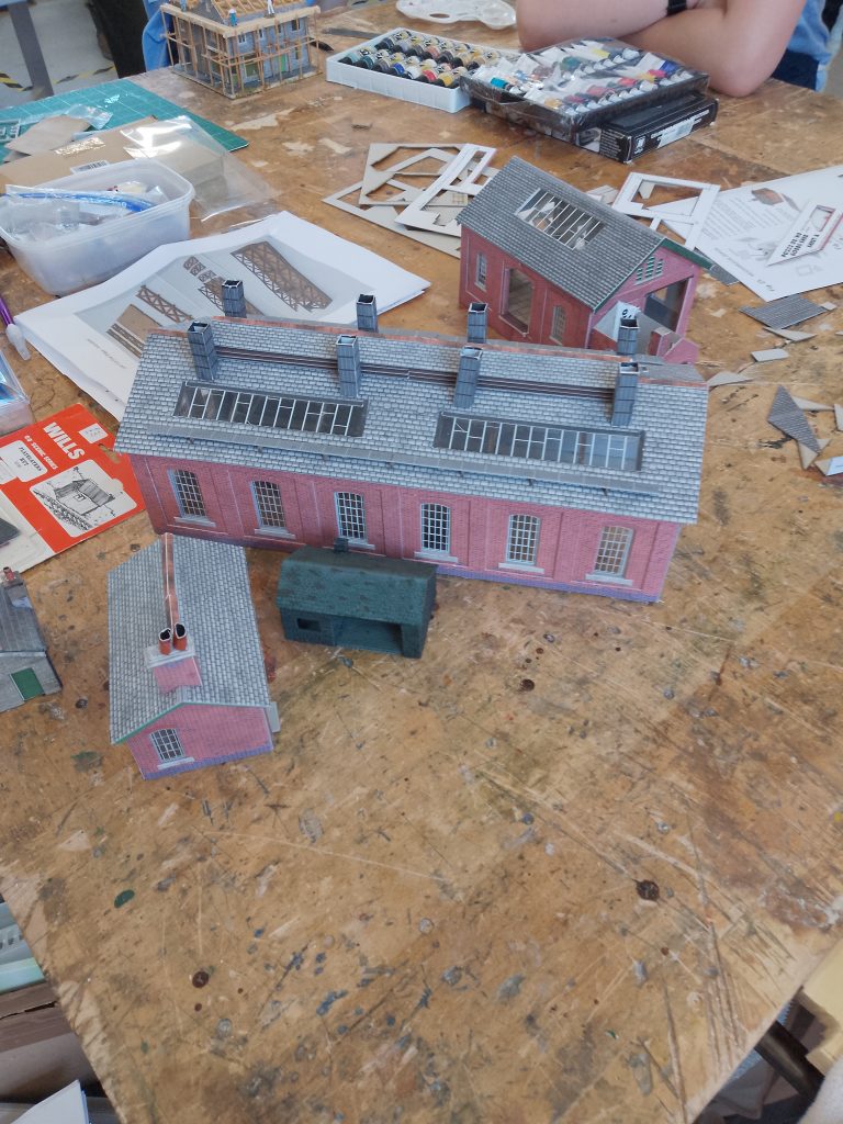
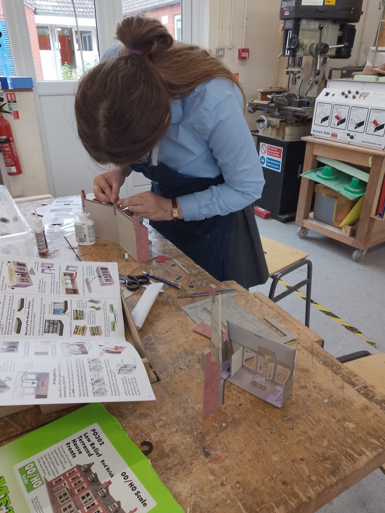
The next few months were taken up by the BMRC members checking & improving the layout electrics and the students, under Rosemaries, tuition set about learning and building the scenic items, engine shed, goods shed, low relief houses etc. As we have come to expect, they learned quickly and produced excellent results. Here are just a few images taken during those sessions.
July and August 2025
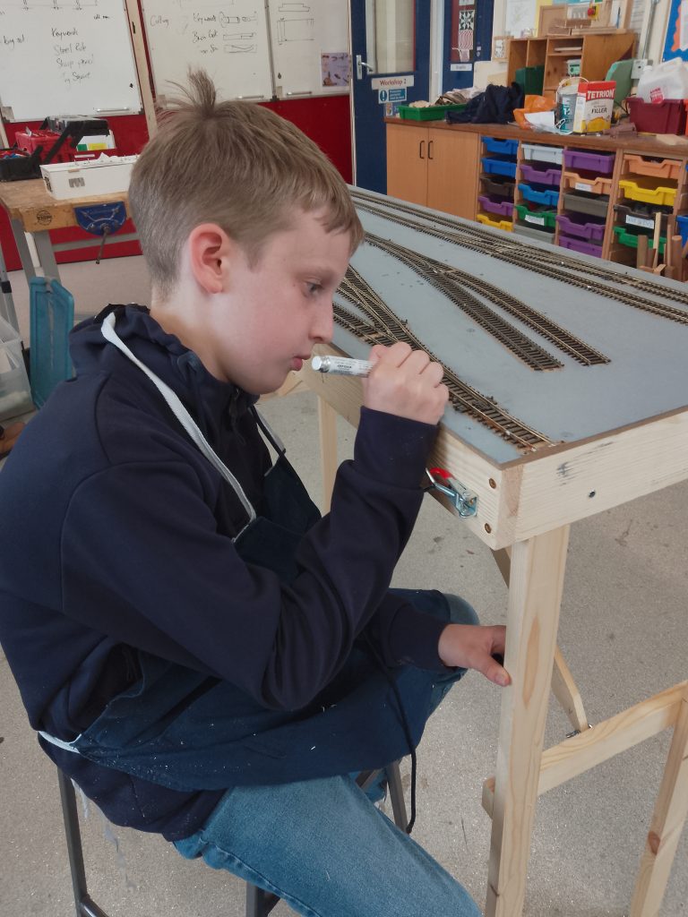
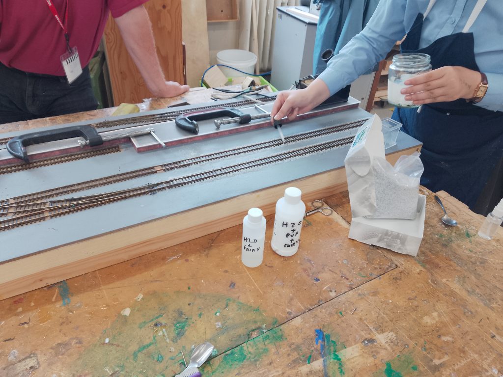
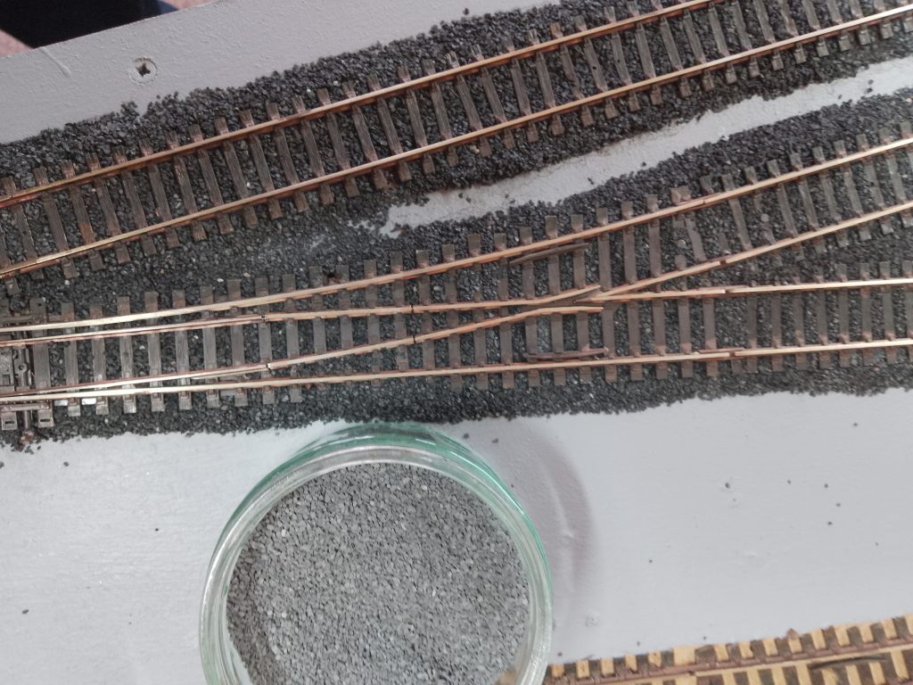
As the end of term approached we moved on with track painting, and ballasting. We had an issue here in that the gray ballast we were using turned almost black after wetting down and gluing but too late to remove it all and start again.
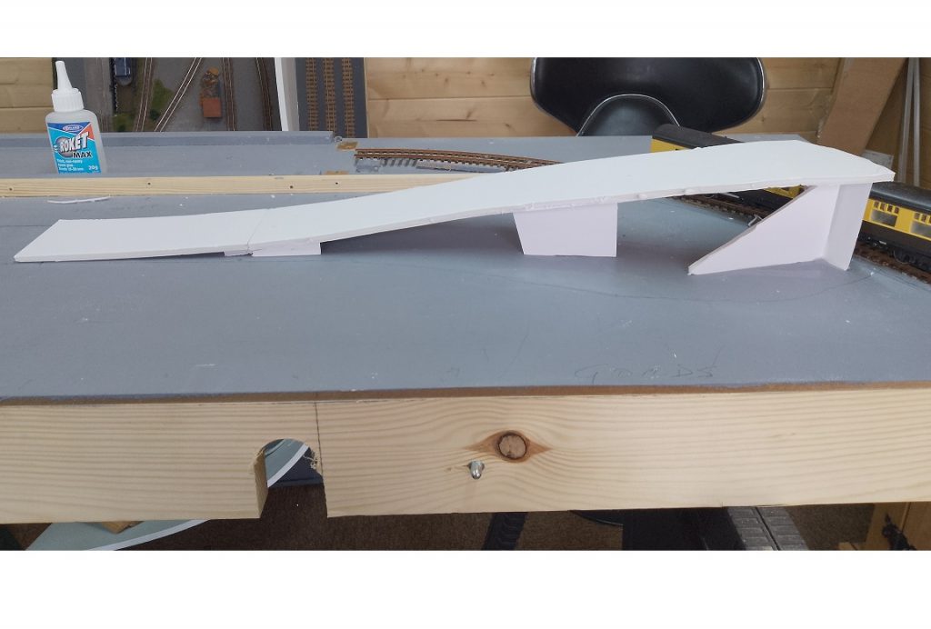
The backscenes were created and painted and placed on the layout. Then the first steps were taken in adding some scenery, first was the feature item, the bridge & roadway over the station approach and into the town area. Formed by cutting foam board to shape, bending carefully and checking the clearances to the approach track. The layout was fully erected and tested and finally the goal was achieved and the layout was exhibited at our Model Railway Show in Stalham on August 24th 2025
Now for the new term, watch this space.
October 2025
The new term is well underway and the first items on the agenda, were some minor track repairs and work on the buildings already constructed. We will be adding lighting to these so some modifications were needed.
The layout is fully erected in the work room so we don’t have to spend time getting it ready each session. The engine shed has been replaced, the old one is in the second hand stall inventory, the new one is quite a bit smaller and will allow for a coaling stage.
In late September the team, including the students, were interviewed by BBC Radio Norfolk and the interview was broadcast on 21st October at 12:30 – but Rosemarie & I missed it due to the dreaded lurgey and the school session had to be cancelled. The BBC provided a link to the program, I recorded it and posted it here:
The After School Club has temporarily closed as the students are fully occupied with other studies and activities, we plan on restarting after the Christmas break. As soon as we can get back to it, we’ll spend some time in training the students to operate the layout and then get on with the scenery, there is quite a bit to do.
January 2026
As of today, the School Project is on hold as not enough students signed up for the after school club this term. We do have an idea for restarting it, more later.
April 2026
A new experience for me, but here we go. I have accepted the responsibility of “Layout Leader” for Hamstal Green, and with help, I expect to make a success of it. Doug Hall and I have a comprehensive project plan which we are eager to get on with. We are told that the layout is scheduled to be on display on May 24th, and we will do our best to make it available.
Big storage box was emptied just to see what was there. Found that boxes and packages had been stacked on top of the buildings, it is such a shame. Spent the evening assessing what needed to be looked at first. Most urgent steps seemed to be a substantial leg for the back corner, plus some track and back scene re-alignment.
New rear leg fitted. Layout levelled on blocks with all leg adjusters at their minimum position. This quickly revealed that the existing leg adjusters were not going to cope, so urgent revision needed. Four legs taken off layout to revise all 8 leg adjusters at home. Extra storage box now in use so buildings are safe, but some repairs will be needed.
All leg frames re-fitted, and layout levelled with difficulty using new adjusters. Curved backboard refitted without gaps, and remaining boards removed so as to refit them with correct alignment. One board taken home to trim and refit. Second attempt to get layout correctly levelled. This time, done with all 4 board latched undone, and latches only closed when all boards stood correct. A much better result.
We have 5 backboards, short left, curved, 2 straight, short right. 3rd backboard added to align with the 2nd backboard after minor correction of the gap. 5th board added at far end, and 4th backboard added so that the 4th / 5th corner joint can be closed easily. This left a 6mm gap between boards 3 and 4. We need to see if this is acceptable. Board 1 refitted so that all gaps close correctly
Visited Norwich Model Railway exhibition on 11th April and looked at lots of backscenes on display. The ones that stood out were made by ID backscenes. Doug and I decided that we go with that for Hamstal Green. Also saw that curved corners on end boards look much better.
Cassettes sanded to make them fit better, but we found that there were connectivity problems. Hold-down clips will be required to clamp the front end of each cassette down to ensure track power connects correctly. Loose track fixed where it connects to the cassette. Power connected, Track power seems to be ok, but not much progress made with the EzyBus controls.
All backscene boards looked at to define problems and removed. Four external hard corners rounded off, they now look much better. Better joints created between back boards 1-2, 3-4, and 4-5. Joint 2-3 will need to be looked at later. All forward facing screw holes filled, and boards sanded ready for back scene papers to be attached. ID-backscenes 203 A-B ordered.
We now have an EzyBus spec to learn and understand, and a partial wiring diagram for the layout. Broken wire found and fixed on one of the control box LED’s. Broken servo actuator arm found and replaced on servo 7. Broken wire found on input module connector A and fixed. 12 volt DC socket for EzyBus on control box found to be suspect and replaced. Most of the EzyBus network is now working, but some adjustment and re-programming will be required. Found that point 1 needed carpentry to get the servo assembly into the correct position, so main board and control box removed to home for revisions and checking. Servo 1 and microswitch removed, main board frame cut away and mechanism fitted in better position. Servo neutral set, and servo arm relocated into correct position, Actuator pin installed and mechanism refined to leave point blades in mid position. EzyBus settings re-programmed for correct actuation range. Some ballast removed from point to give free movement. Microswitch re-fitted and frog changeover checked ok.
Points 2 to 6 all re-programmed for correct actuation range. Point 7 mechanism moved for better location, blades checked for neutral position ok. Actuator arm badly fitted, revised ok. Found actuator pin was binding in one direction, hole extended, and all tested ok. Re-programmed. LED indications on control box checked ok. All of board 1 now functioning ok, but no trains have been run yet. Left and right settings noted for all points on the board.
Same exercise will be carried out on 2nd board on Friday May 1st.