
This is a Club Members Layout originally built by a team of Club members and now in private hands
This layout was originally constructed as part of a quarry/mining environment by another club but was abandoned before completion. Broadland Model Railway Club acquired it as just the two left hand baseboards with almost no scenery and all the electrical wiring removed.
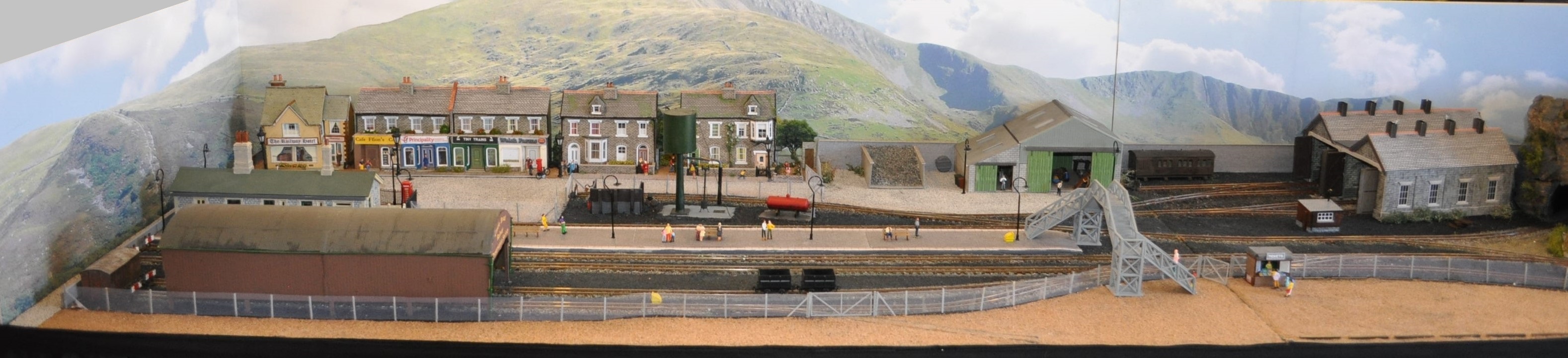
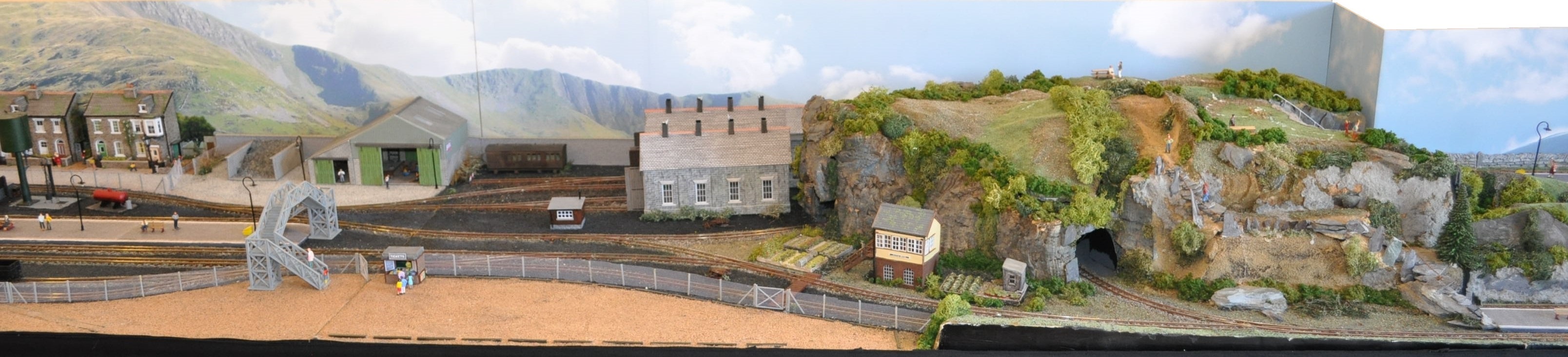
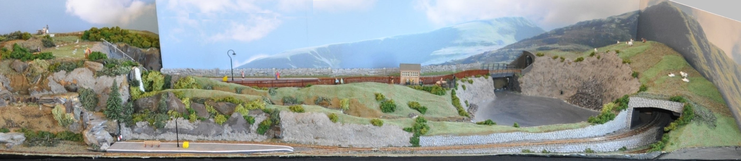
It was extended by one more baseboard incorporating the disused quarry, lake and the fiddle yard. The layout is now presented as a current day preserved railway under the name “Castle Broad Railway Preservation Society” and this provides much scope for a variety of stock. It is loosely based on the railway at Llanberis in North Wales; in fact the back scene is a photo of Llanberis but with a subtle change – can you spot it?
The layout was originally wired using the DC system, separated into 4 ‘cabs’ equating to the four main sections: Main Station and Carriage sidings; Engineering Works and Engine Shed; Lake End Loop and Fiddle Yard; and the branch line to the Mountain. All points are operated by Peco PL-10 motors and we have incorporated working semaphore signals using small servos and programmable circuit boards using Arduino Nanos.
December 2024
The layout has now been purchased by a Club member who was part of the team that built it back in 2018 and it is planned to convert the control system to DCC with servo operated points and signalling using the MERG EzyBus system. This will greatly simplify the wiring as a result. The layout may be available for exhibition in the future – watch this space.
November 2025
Finally work has begun on the conversion to DCC and the first steps involve getting the plans and materials right. It has been decided to replace the original two control panels into one panel which will be 3 feet long. To this end a new track plan has been created by merging the old mimic panel diagrams into one and this will be printed onto vinyl to form the new mimic panel. From this we can determine the materials needed to provide the controls.

December 2025
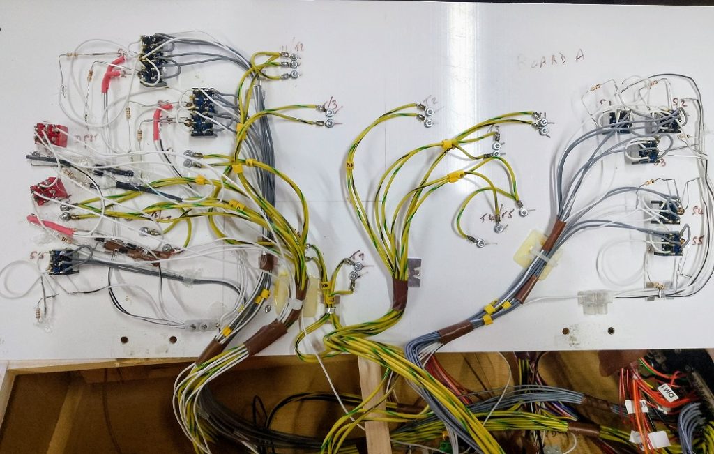
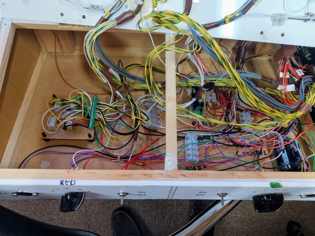
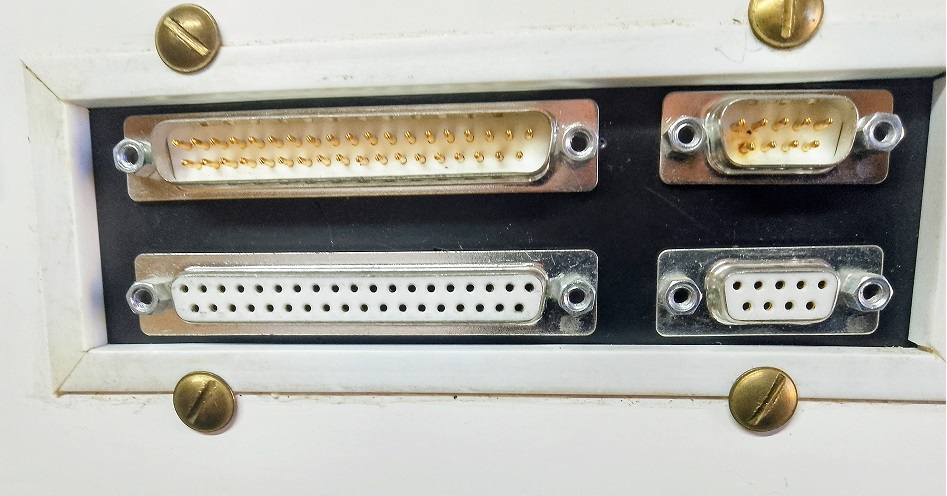
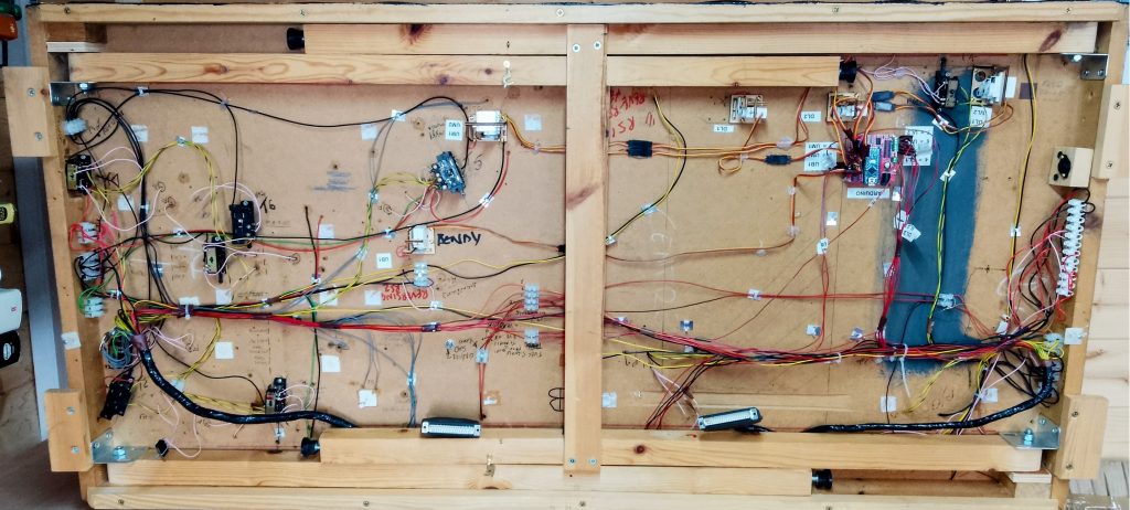
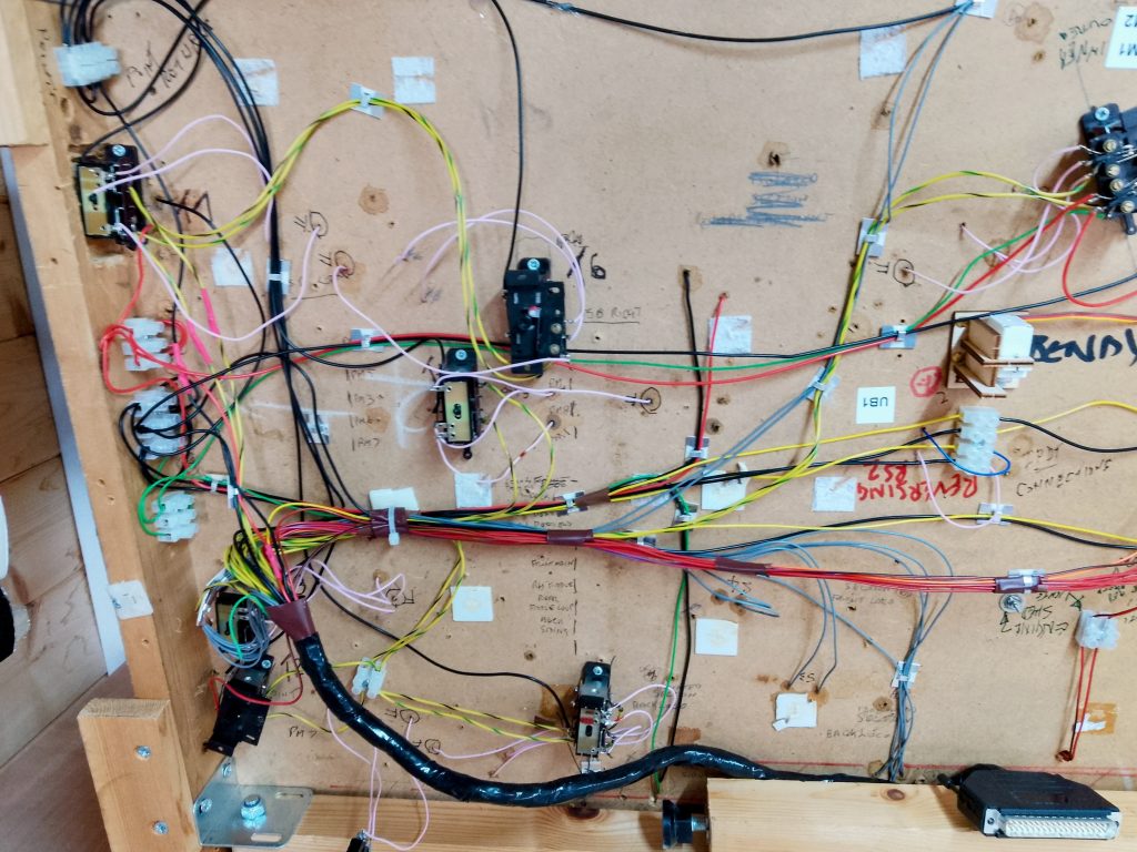
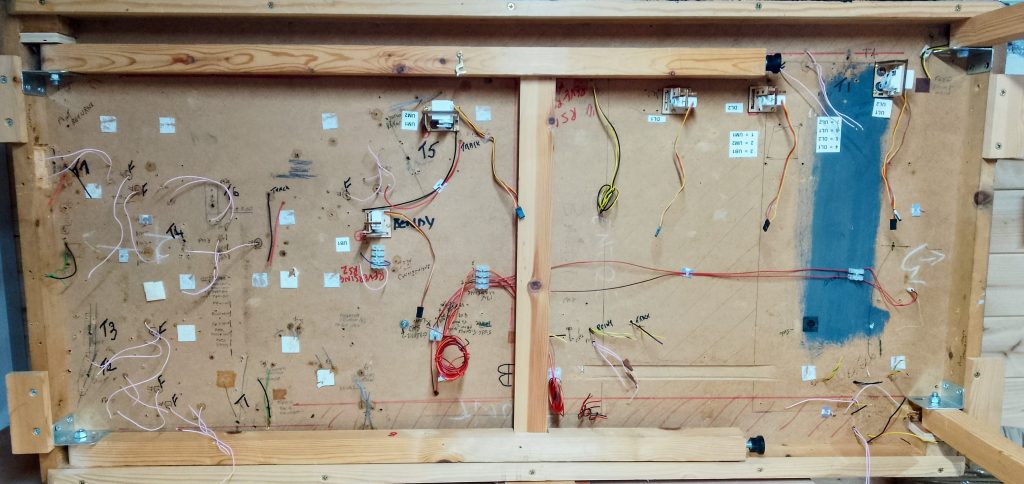
For those who do not yet understand the DC vs DCC arguments I show below the wiring required on the original DC layout. These images are from one of two identical control panels, this one controls the left hand half of the diagram above. All of the grey wires are for operating the isolation sections, the yellow/black yellow/green are to operate the points and the rest are either track feeds via rotary cab switches or the control connections to the Arduino boards for the signal. The end panel shows the connections to the actual baseboards – two DB37 and two DB9 multiplugs; the DB9s are for the 12vdc and 16vac transformer connections and the DB37s are all the rest. Total solder connections required = 4 x 37 + 4 x 9 = 184! Double this for the second panel and you have 368 solder joints. Using DCC for track control and the EzyBus I2C bus requires a total of 7 wires from panel to board; 3 boards results in 70 solder joints a huge reduction. And, we will be able to add more EzyBus modules to control other features without adding a single wire to the panel to board connections.
February 2026
Work commenced on the first baseboard – actually the middle one – and careful removal all the point motors and associated wiring. Next the track feeds were removed after trying to figure out what various modifications have done. It seems I will have to work on the point frogs to ensure proper insulation from the departing tracks as well as removing the over-centre springs from the tie bars. This is essential when using servos as the spring takes over while programming the blade positioning.
Exhibition Requirements
| Layout Size | 12′ x 2′ |
| Operating space | 15′ x 5′ |
| Number of operators | One or two |
| Number of cars to transport | One or two |
| Maximum distance for travel | Negotiable |
| Tables & chairs required | 1 table, 2 chairs |